Sunday, February 23, 2020
Basic Cisco Router Configuration Step-By-Step Commands
https://www.networkstraining.com/basic-cisco-router-configuration-steps/
Basic Cisco Router Configuration Step-By-Step Commands
This post is by no means an exhaustive tutorial about Cisco Routers and how to configure their numerous features. It is a step-by-step guide for the most basic configuration commands needed to make the router operational.
When you first power up a new Cisco Router, you have the option of using the “setup” utility which allows you to create a basic initial configuration.
However, in this post I will show you how to do this basic setup with the Command Line Interface (CLI).
Mastering the Cisco Router CLI is essential for more complex configuration tasks and it is the most important knowledge you should acquire if you want to become a Cisco network administrator.
CLI Configuration Modes
The basic CLI modes that we will be referring below are as following:
Router> <– User EXEC Mode
Router# <– Privileged EXEC mode
Router(config)# <– Global Configuration Mode
Router(config-if)# <– Interface Configuration Mode
Router(config-line)# <– Line Configuration Mode
Router# <– Privileged EXEC mode
Router(config)# <– Global Configuration Mode
Router(config-if)# <– Interface Configuration Mode
Router(config-line)# <– Line Configuration Mode
I assume that you already have some basic knowledge of CLI and how to navigate between different configuration modes (user mode, privileged exec mode etc), so let’s get started:
Step-by-Step Configuration of Cisco Routers
Step1: Configure Access Passwords
The first step is to secure your access to the router by configuring a global secret password and also passwords for Telnet or Console as needed.
Enter into Global Configuration mode from the Privileged EXEC mode:
Router# configure terminal <– Privileged EXEC mode
Router(config)# <– Global Configuration Mode
Router(config)# <– Global Configuration Mode
In Global Configuration Mode you configure parameters that affect the whole router device. Here we will configure the Enable Secret password that you will be using from now own to enter into Privileged EXEC Mode from User EXEC Mode.
Router(config)# enable secret “somestrongpassword”
From now on, when you log in from user EXEC mode you will be asked for a password.
It is suggested also to configure a password for the Telnet Lines (VTY lines) which will secure your access when connecting via Telnet over the network.
Router(config)# line vty 0 4
Router(config-line)# password “strongTelnetPass”
Router(config-line)# login
Router(config-line)# password “strongTelnetPass”
Router(config-line)# login
Some people prefer to create also local user accounts (usernames and passwords) on the router itself in order to authenticate to the device. Here I’m explaining how to configure this specific setup.
Step2: Configure a Router Hostname
To differentiate your Router from other devices in the network, you should configure a Hostname for your device.
Router(config)# hostname My-Router
My-Router(config)#
My-Router(config)#
Notice that your Router prompt changes to the new hostname that you have just set.
Step3: Configure IP addresses for Router Interfaces
This is an essential step in order for your router to be able to forward packets in the network. The most basic parameter for a Router Interface is the IP address. From Global Configuration Mode you need to enter into Interface Configuration Mode:
My-Router(config)# interface GigabitEthernet 0/0
My-Router(config-if)# ip address 100.100.100.1 255.255.255.252
My-Router(config-if)# no shutdown
My-Router(config-if)# exit
My-Router(config-if)# ip address 100.100.100.1 255.255.255.252
My-Router(config-if)# no shutdown
My-Router(config-if)# exit
My-Router(config)# interface GigabitEthernet 0/1
My-Router(config-if)# ip address 192.168.10.1 255.255.255.0
My-Router(config-if)# no shutdown
My-Router(config-if)# exit
My-Router(config-if)# ip address 192.168.10.1 255.255.255.0
My-Router(config-if)# no shutdown
My-Router(config-if)# exit
Step4: Configure Routing (Static or Dynamic)
The Router’s main purpose is to find the best route path towards a destination network and forward packets according to the best path.
There are two main ways a router knows where to send packets. The administrator can assign static routes, or the router can learn routes by using a dynamic routing protocol.
For simple network topologies, static routing is preferred over dynamic routing. Let’s see how to configure static routes from Global Configuration Mode.
My-Router(config)# ip route [destination network] [subnet mask] [gateway]
My-Router(config)# ip route 200.200.200.0 255.255.255.0 100.100.100.2
The command above tells the router that network 200.200.200.0/24 is reachable via gateway address 100.100.100.2.
Another popular static route that we usually configure on Internet Border routers is the default static route:
My-Router(config)# ip route 0.0.0.0 0.0.0.0 100.100.100.2
The default static route above instructs the router to send ALL packets that the router does not have a more specific route entry to gateway address 100.100.100.2 (which might be the ISP gateway address).
Step5: Save your configuration
Save your current running configuration into NVRAM. This will overwrite the startup configuration.
My-Router(config)# exit
My-Router# copy running-config startup-config
My-Router# copy running-config startup-config
You can display your current configuration to verify your settings as following:
My-Router# show running-config
Step 6 (optional): Configure NAT
This step is optional and is required only if your router acts as Internet border gateway to provide access to the internal private LAN towards the Internet.
Assume that interface GigabitEthernet 0/0 is the WAN interface (connected to ISP for Internet access) and interface GigabitEthernet 0/1 is the LAN interface connected to the internal network.
My-Router# conf term
My-Router(config)# interface GigabitEthernet 0/0
My-Router(config-if)# ip nat outside
My-Router(config-if)# exit
My-Router(config)# interface GigabitEthernet 0/0
My-Router(config-if)# ip nat outside
My-Router(config-if)# exit
My-Router(config)# interface GigabitEthernet 0/1
My-Router(config-if)# ip nat inside
My-Router(config-if)# exit
My-Router(config-if)# ip nat inside
My-Router(config-if)# exit
The commands above tell the router that traffic entering GigEth 0/1 will be NAT translated. Also, traffic exiting GigEth 0/0 will also be NAT translated.
Now we need to create an Access List which will identify which specific traffic will be translated using NAT. Assuming that the internal LAN network is 192.168.10.0/24 :
My-Router(config)# access-list 1 permit 192.168.10.0 0.0.0.255
My-Router(config)# ip nat inside source list 1 interface GigabitEthernet 0/0 overload
My-Router(config)# ip nat inside source list 1 interface GigabitEthernet 0/0 overload
The commands above will create a NAT overload (PAT) rule which tells the router to translate any address identified in Access List 1 to the address assigned to GigabitEthernet0/0. The overload keyword allows one public address to be shared among several private internal addresses.
Step 7 (optional): Configure DHCP
A Cisco router can be configured as a DHCP server to assign IP addresses dynamically to internal hosts. First we need to create a pool of IP addresses that will be used to assign to clients:
! Configure the DHCP pool to assign addresses to internal hosts
ip dhcp pool lan-pool
network 192.168.10.0 255.255.255.0
default-router 192.168.10.1
dns-server 8.8.8.8
ip dhcp pool lan-pool
network 192.168.10.0 255.255.255.0
default-router 192.168.10.1
dns-server 8.8.8.8
Then, exclude which IP addresses you don’t want to be assigned by the router:
! Do not assign addresses 1 to 50
ip dhcp excluded-address 192.168.10.1 192.168.10.50
ip dhcp excluded-address 192.168.10.1 192.168.10.50
How to connect to a Router in order to Configure it:
You can connect to a Cisco IOS Router either directly or remotely. For the first time when the device is not configured yet, you usually connect directly with a console cable via the CON port.
The console cable connection is also called “out of band” connection method. After you configure the router and assign IP addresses to its interfaces, you can connect to the router from the network with an “in-band” connection method using Telnet or SSH. Note however that Telnet uses clear-text communication whereas SSH uses encrypted traffic, therefore SSH is preferred.
Router Configuration Modes
After connecting to a Cisco Router (let’s say using a console), you are presented with the Command Line Interface in which you type and enter configuration commands.
After typing a command, you press enter and the command is automatically active on the device. For example using the “shutdown” command on an interface, automatically disables the interface. Now, there are two Router Configuration Modes (or access modes):
- User EXEC Mode: Allows the administrator to access only limited monitoring commands. You can not actually make any configurations from this mode. The command prompt on this mode is “router>”
- Privileged EXEC Mode: Allows the administrator to access all device commands, such as those used for configuration and management, and can be password protected to allow only authorized users to access the device at this “full-access” level. This mode is also called enable mode because you get to it with the enable command. The command prompt on this mode is “router#”. From the privileged EXEC mode you can start configuring the device by typing “configure terminal“
Router Memory Types
A Cisco router has four memory types:
- ROM: This is where the POST script of the router is located. The POST software (Power On Self Test) is used during startup to perform the initial hardware checking of the device. The ROM also holds a mini-IOS used for password recovery.
- RAM: This is where the running configuration is located. After the device boots up, the IOS software is loaded into RAM. Also, RAM holds routing tables, network parameters during operation etc. When configuring the router, we actually change the running-configuration which as we said is stored into RAM
- NVRAM: When we save the running-configuration (using the command “write“) it is stored into the NVRAM and becomes the startup-configuration. After rebooting the router, the startup-configuration is loaded from the NVRAM.
- Flash: This is like the hard-disk of a PC. It holds the IOS software image file and any backup configurations that you might save from time to time.
When you issue the “show running-configuration” command on the router you instruct the device to display the current running configuration in RAM. When you issue the “show startup-configuration” command you instruct the router to display the stored configuration in the NVRAM.
Related Posts
- How to Configure Static Routing on Cisco IOS Routers (Examples)
- Redistribution Between Cisco EIGRP into OSPF and Vice Versa (Example)
- Configuring Local Username and Password on a Cisco IOS Router
- How to Configure DHCP on Cisco Routers (With Command Examples)
- Lan-to-Lan IPSEC VPN Between Cisco Routers – Configuration Example
Friday, February 21, 2020
Network Components
https://techacad4u.blogspot.com/p/network-components.html
Types of Network Components:

Functions of End Devices

Intermediary Devices

Functions of Intermediary Devices

Network Media
Communication across a network is carried on a medium.
The medium provides the channel over which the message travels from source to destination.
Three types of media

Types of Network Components:
- Devices
- Media
- Services
Network Devices are physical devices which are helped in communication between hardware on a computer network
There are two types of Devices- End Devices
- Intermediary Devices
End Devices are a Source or a Destination Device in a Network. In Easy way we can say the device at the end of the Network is called End Devices
End Devices are the interface between the human and communication network
Here we can some of the End Devices used in our Communication Network.End Devices are the interface between the human and communication network
Functions of End Devices
Intermediary Devices
Intermediary devices interconnect end devices.
These devices provide network connectivity and ensure that data flows across the network.
Intermediary devices connect the individual hosts to the network.
Here we can some of the Intermediary Devices used in our Communication Network.These devices provide network connectivity and ensure that data flows across the network.
Intermediary devices connect the individual hosts to the network.
Functions of Intermediary Devices
Network Media
Communication across a network is carried on a medium.
The medium provides the channel over which the message travels from source to destination.
Three types of media
- Copper
- Fiber Optics
- Wireless
How to configure a Switch Virtual Interface
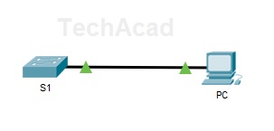
Topology

Step 1: Design the topology as per the topology diagram given above.
Step 2: Connect to Switch Console port andPC RS232 Port
Step 3: Go to PC ->Terminal ->Ok
Switch>enable
Switch#configure terminal
Switch(config)#interface vlan 1
Switch(config-if)#ip address 192.168.1.254 255.255.255.0
Switch(config-if)#no shutdown
|
Step5: Configure the PC with IP Address: 192.168.1.10, Subnet Mask: 255.255.255.0
Step 6: Connect to switch FastEthernet0/1 port and PC FastEther0 using a Straight through Cable.
Step 7:Verify Network Connectivity
ping from PC to Switch
ping from PC to Switch
Ping 192.168.1.254 |
Show Commands used:
Switch#show running-config
Switch#showip interface brief
|

CCNA-ICND1
| ICND1 | |
|---|---|
| SL No. | Topic |
| ICND1.1 | Peer-to-Peer Network |
| ICND1.2 | Network Components |
| ICND1.3 | How to configure a Switch Virtual Interface |
| ICND1.4 | Basic Configuration of a CISCO Switch |
| ICND1.5 | Configure a Simple Network Using Packet Tracer |
TUTORIAL || How to Make a Simple Network Simulation Using Cisco Packet Tracer Application
https://steemit.com/utopian-io/@bangkimo/tutorial-or-or-how-to-make-a-simple-network-simulation-using-cisco-packet-tracer-application
1.Open the cisco packet tracer application
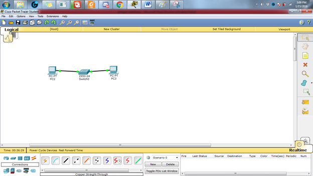
2.Simple Network Installation Preparation in this example is to use two workstations and 1 switch. Each node is connected to the cable so it looks in accordance with Figure 3:
----1.Select the icon of the PC that sits in the left corner and then put on display
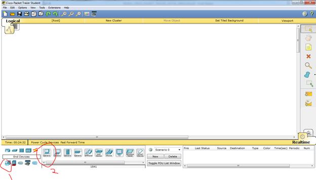
----1.Select the icon of the PC that sits in the left corner and then put on display
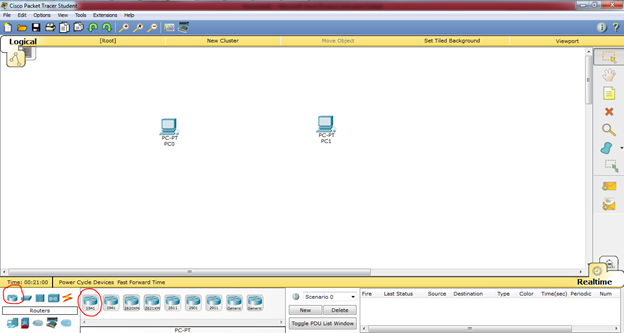
----2.Place the 2 pieces on the PC display

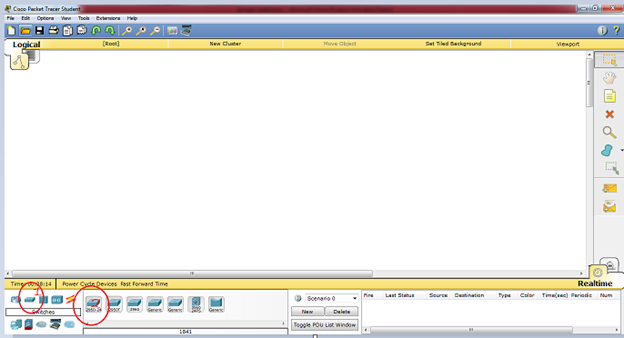
----3.Next select switch and put on display
----4.Slanjutnya the process of wiring to connect 2 PC, select the straight cable, create an image such as this, when the wires yet is green then the PC yet connect
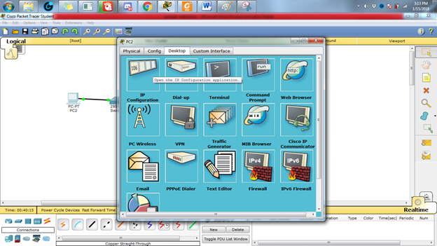
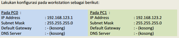
3.And then do the configuration IP address host PC0 by means of double-click image PC0, then click the tab of the Desktop and choose menu section the IP Configuration so that the display is visible on the picture below This
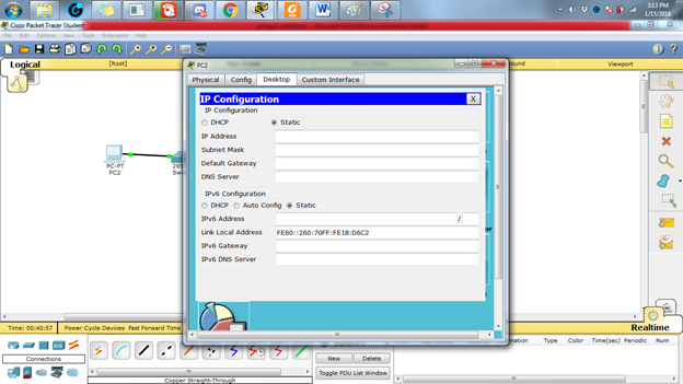
4.Add the IP Address 192.168.123.1 and Subnetmask will come out automatically
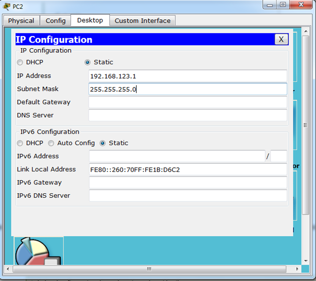
5.Do the same on the workstation configuration is as follows: each PC with a different ip address
6.PING
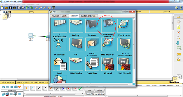
To test the connection between the two nodes using the "ping" utility. To start the ping from PC0 PC1 headed, double-click the PC0 making it appear properties window for PC0, then select the tab of the Desktop, then select the menu Command Prompt so that it appears look like Figure 5 below.
To test the connection between the two nodes using the "ping" utility. To start the ping from PC0 PC1 headed, double-click the PC0 making it appear properties window for PC0, then select the tab of the Desktop, then select the menu Command Prompt so that it appears look like Figure 5 below.
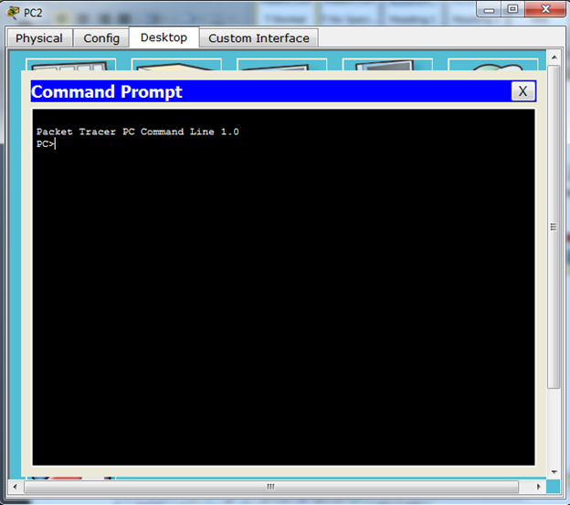
7.Do a "ping" by way of typing: ping [ip_address_target] to do ping towards PC1 which has IP address 192.168.123.2 is by way of type in: ping 192.168.123.2
If the configuration you do is correct then the produced output like this:
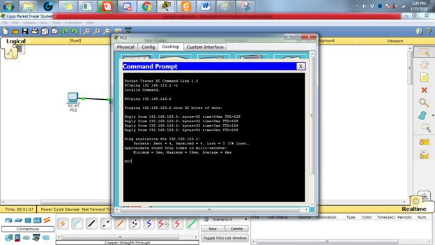
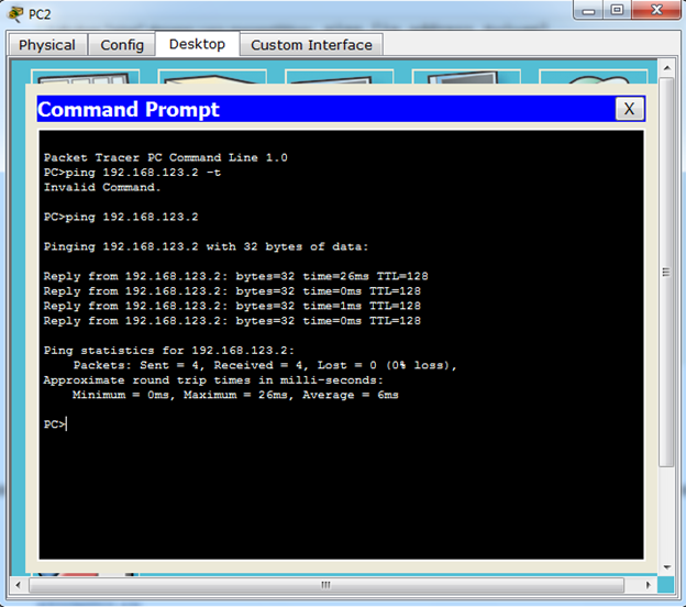
If the configuration you do is correct then the produced output like this:
CONCLUSION
From the results of experiments conducted, it can be concluded that:
From the results of experiments conducted, it can be concluded that:
- The new PC0 and PC1 workstations can be connected if both workstation IP addresses have been well configured and correct.
- To test connectivity between nodes can use the "ping" command.
Results ping command output there are various kinds.
Namely: Reply, Request Timed Out, andDestination Host Unreachable.
Basic Configuration of a CISCO Switch
https://techacad4u.blogspot.com/p/basic-configuration-of-cisco-switch.html

Download the Packet Tracer Activity File
Objectives
Part1: Configure PC
Part2: Configure a Basic Switch Configuration
Part3: Verify the Connectivity
Part2: Configure a Basic Switch Configuration
Part3: Verify the Connectivity
Topology
Step1: Assign IP address 192.168.1.10 and subnet mask as 255.255.255.0 for PC
(Completion: 15%)
Part2: Configure a Basic Switch Configuration(Completion: 15%)
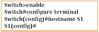
Step 1: Assign a name to a switch.To configure parameters on a switch, you may be required to move between various configuration modes.
Configure the switch name as S1(Completion: 23%)
Step 2: Secure privileged mode access.Set the enable secret password as techacad (Case Sensitive for scoring Mark)
(Completion: 30%)

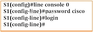
Step 3: Secure access to the console line.
To secure access to the console line, access line mode and set the console password to cisco
(Completion: 46%)
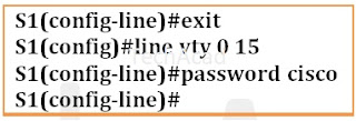
Step 4: Secure access to the vty line.To secure access to the vty line, access line mode and set the vty password to cisco
(Completion: 53%)
Step 5: Encrypt the console and vty passwords.
(Completion: 61%)

Step 6: Configure a message of the day (MOTD) banner.Configure the Banner Message as Warning
(Completion: 69%)

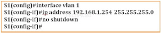
Step 7: Configure Switch Virtual InterfaceConfigure VLAN 1 with ip address 192.168.1.254 and subnet mask 255.255.255.0
Bring the VLAN 1 interface state to up
(Completion: 92%)
(Completion: 92%)
Step 8: Save Configuration Files to NVRAM
(Completion: 100%)

Part3: Verify the Connectivity


install mcOS Version Cisco Packet Tracer 7.2.1,
In this video I'll tell you how to download and install mcOS Version Cisco Packet Tracer 7.2.1, which is the latest version at the time of uploading this video, on macOS High Sierra or Mojave directly without using Wineskin. I'll also tell you very briefly how to check if your mac is 32-bit or 64-bit. Please go to https://www.netacad.com to download your Cisco Packet Tracer file for free, which is the number one trusted website for downloading packet tracer files.
How to install Cisco Packet Tracer on Mac Os X
Subscribe to:
Comments (Atom)

-
 https://techacad4u.blogspot.com/p/network-components.html Types of Network Components: Devices Media Services Network Devices are ph...
 -
https://www.networkstraining.com/basic-cisco-router-configuration-steps/ Basic Cisco Router Configuration Step-By-Step Commands This ...
-
https://www.sysnettechsolutions.com/en/install-cisco-packet-tracer/ On September 11, 2019, Cisco Networking ...
