
1.Open the cisco packet tracer application

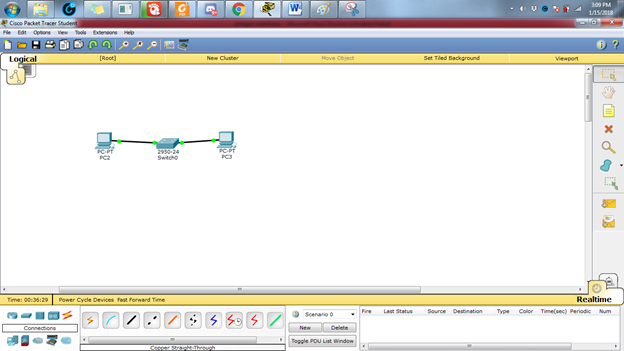
2.Simple Network Installation Preparation in this example is to use two workstations and 1 switch. Each node is connected to the cable so it looks in accordance with Figure 3:
----1.Select the icon of the PC that sits in the left corner and then put on display
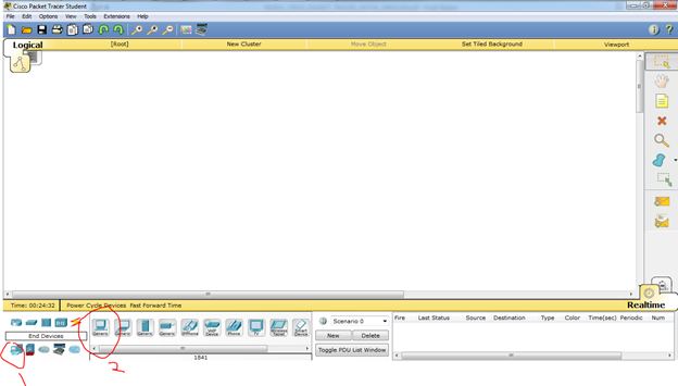
----1.Select the icon of the PC that sits in the left corner and then put on display
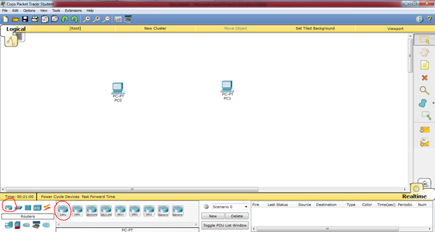
----2.Place the 2 pieces on the PC display

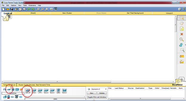
----3.Next select switch and put on display
----4.Slanjutnya the process of wiring to connect 2 PC, select the straight cable, create an image such as this, when the wires yet is green then the PC yet connect
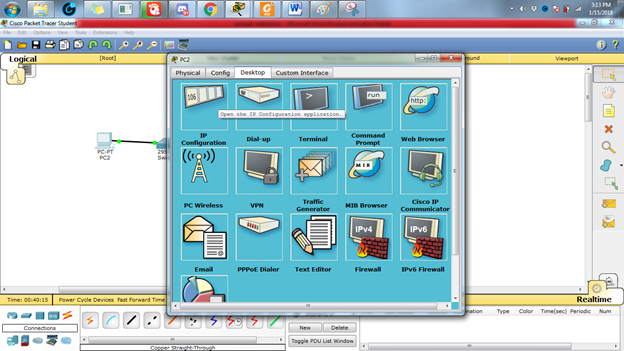
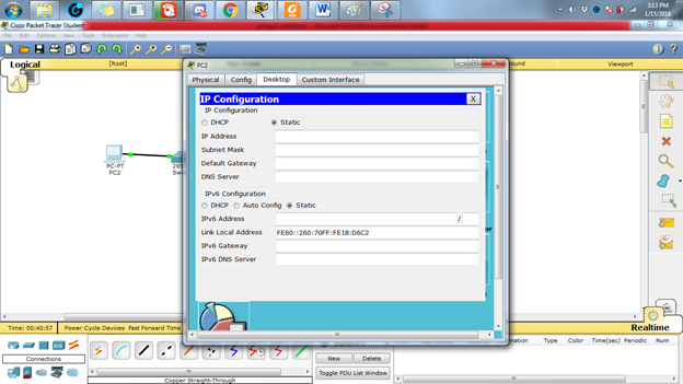
3.And then do the configuration IP address host PC0 by means of double-click image PC0, then click the tab of the Desktop and choose menu section the IP Configuration so that the display is visible on the picture below This
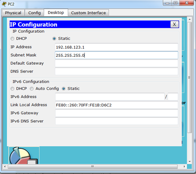
4.Add the IP Address 192.168.123.1 and Subnetmask will come out automatically
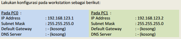
5.Do the same on the workstation configuration is as follows: each PC with a different ip address
6.PING
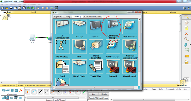
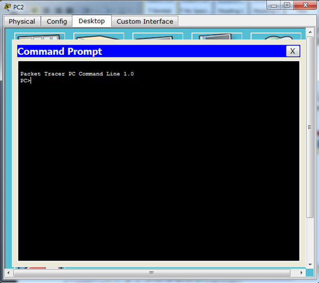
To test the connection between the two nodes using the "ping" utility. To start the ping from PC0 PC1 headed, double-click the PC0 making it appear properties window for PC0, then select the tab of the Desktop, then select the menu Command Prompt so that it appears look like Figure 5 below.
To test the connection between the two nodes using the "ping" utility. To start the ping from PC0 PC1 headed, double-click the PC0 making it appear properties window for PC0, then select the tab of the Desktop, then select the menu Command Prompt so that it appears look like Figure 5 below.
7.Do a "ping" by way of typing: ping [ip_address_target] to do ping towards PC1 which has IP address 192.168.123.2 is by way of type in: ping 192.168.123.2
If the configuration you do is correct then the produced output like this:
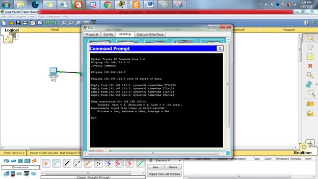
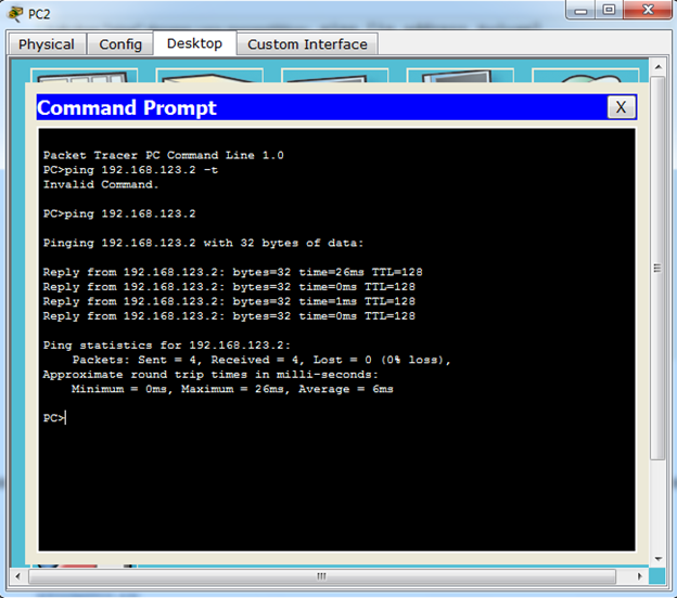
If the configuration you do is correct then the produced output like this:
CONCLUSION
From the results of experiments conducted, it can be concluded that:
From the results of experiments conducted, it can be concluded that:
- The new PC0 and PC1 workstations can be connected if both workstation IP addresses have been well configured and correct.
- To test connectivity between nodes can use the "ping" command.
Results ping command output there are various kinds.
Namely: Reply, Request Timed Out, andDestination Host Unreachable.


No comments:
Post a Comment